Lung Airway Geometry
Lung Airway Geometry 1 Heading link
Airway Generation
For each airway insonification model we create, a lung model complete with airways need to be generated. In this section, we will discuss how this happens
The Design Process
Our airway insonification models are theoretical models, meaning they are digital representations of real lungs and airways developed on a computer. This is done so we can simulate the acoustic environment of the lungs without needing to excise the lungs and airways. These theoretical models are compared to experimental models through use of finite element (FE) analysis.
Airway insonification models typically incorporate two geometrical parts: the lungs and airway structure. In the AVL, we utilize two main approaches to developing lung models: image based segmentation, and programmatic methods. In both cases, CT/MRI is used, however the methodology of developing the models is different. In this part of the process, image based segmentation methods were compared to programmatic methods with the purpose of finding what is the optimal way to develop theoretical models quickly and most efficiently. Image based segmentation methods were compared against a combination of tracing and programmatic means
In the case of image based segmentation, the lungs and airways are segmented (meaning partitioned from the original image in order to make it easier to analyze). In this step, the boundaries of the lungs and airways are traced and converted into a system of surfaces. These surfaces can then be exported and brought into another tool for FE model development (namely, volume meshing).
Lung Airway Geometry 2 Heading link
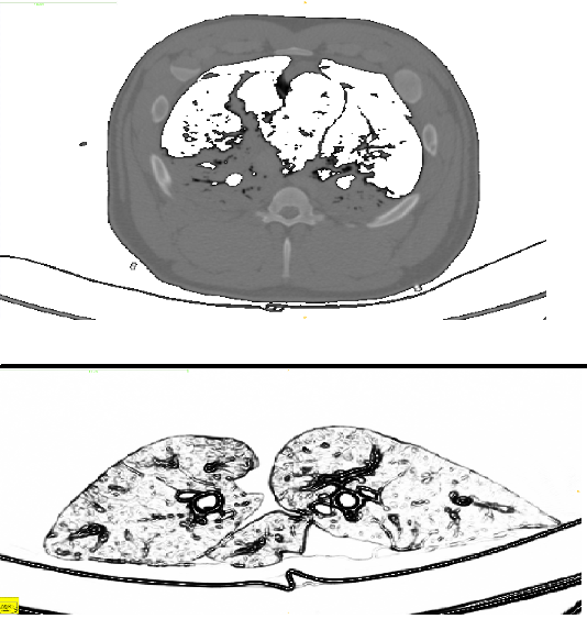
(bottom) An axial CT image of a full pig torso. In this axial image, the lungs and airway structure can be seen, with the addition of other internal structures like the ribcage, scapula (not shown) and torso parenchyma.
Model Development through Image Based Segmentation
When a CT/MRI scan takes place, a stack of images are produced that represent the internal structure of the object placed in the scanner. In our case, a set of excised porcine lungs and airways, along with some full pig torsos, were placed in a clinical CT scanner at Rush University Medical Center and a 3D volume set was obtained and exported. This exported image data was then used for image base segmentation.
In the case of image based segmentation, a set of structures of interest are extracted. The extraction can be done in a variety of ways: manually tracing a image stack is one of the most common, although more automated means through bounded balloon expansion or segmentation through contrast values are becoming more commonplace.
The image segmentation step was performed in ITK SNAP[1], an open source tool which provides excellent segmentation functionality. In ITK-SNAP, an automatic registration was performed on both the excised lungs and the full pig torso model in order to develop two separate finite element models: one that incorporates just the lungs and airways, and another that incorporates the lungs and airways along with the ribcage, scapula and torso parenchyma. Accordingly, experimental airway insonification data was collected on a excised set of porcine airways and full pig torso, in order to provide an experimental comparison for the theoretical models. In this way, we hope to validate the theoretical models and provide proof for their use.
The segmentation was done both automatically and manually: the Snake Algorithm was used on the larger airway segments, and manual tracing was done on higher order airway segments with smaller diameter. The bone, lungs and torso parenchyma were segmented by tracing a boundary region of the region of interest.
Lung Airway Geometry 3 Heading link


(left) A segmentation of the airways. (center) A segmentation of the lungs with the airways placed in.
(right) A separate segmentation of a full pig torso model with the torso not shown.
These theoretical models were then volume meshed and exported to COMSOL Multiphysics for simulation. In this step, image based segmentation was the only method used to develop the geometry, and by extension, theoretical models. Using only image based segmentation, you can get accurate geometry, but there are a few problems associated with this method.
- At the resolution limit, it is hard to interpret airway geometry.
- CT imaging is not perfect: breaks in contrast can cause discontinuous geometry.
- A complicated surface makes FE modeling difficult.
With the first listed problem, the number of airway segments segmented (and by extension the complexity of the tree) is limited to what you can see with the CT/MRI scanner. Put in context, collapsed airways or airways with smaller diameters typically show up very faintly if at all. The second and third problems can be addressed in a few ways, but all of them typically involve manual post-processing methods. All of these post-processing methods add a considerable amount of time to model development, which brings up the question: can this be done more efficiently and faster?
Lung Airway Geometry 4 Heading link
Model Development through a Hybrid Tracing/Programmatic Method
In contrast to image based segmentation, programmatic methods provide a statistically relevant geometry quickly. Put in context, it has a similar branching structure, set of lengths and radii, and branching angles, but it differs from image segmentation based methods in the aspect that its artificial: the actual airway structure may bifurcate in different locations, or the lengths and radii of some segments may be slightly different. Statistically relevant implies that when an average across all segments from a given generation is compared against segmentation based methods and the hybrid method, the lengths, radii and bifurcation angles will be similar.
In this study, Constrained Constructive Optimization (CCO)[2] was used to develop base. CCO utilizes a power law relationship to relate flow to diameter, and is an iterative process involving random point selection and iterative optimization.


(left) A 1D point and connectivity traced tree showing the “backbone” of the airway structure.
(right) The 1D tree shown on the right with attributed radii.
CCO is a programmatic method that can grow any number of segments to an inputted tree. Before CCO can be used, it has to be initialized with an input geometry and perfusion volume. The input geometry is a cylindrical tree, and the perfusion area of volume is a FE mesh. Once the tree has been inputted, CCO can then grow an arbitrary number of airway segments inside the perfusion volume defined by the mesh. In this study, tracing was performed on the same CT images used to segment the lungs and airways in the segmentation to create a 1D “base” tree that was then inputted to have CCO grow and expand on.
There are no trees now, but here are some that look cool developed by Kitaoka[3] that have ~55,000 segments.


(left) An airway tree developed through Kitaoka’s Power Law code with ~55,000 airway segments.
(right) The same tree shown to the left, with a closeup showing the fractal pattern of the airway structure